
CUT IT
From Approved Files to CNC-Machined Parts
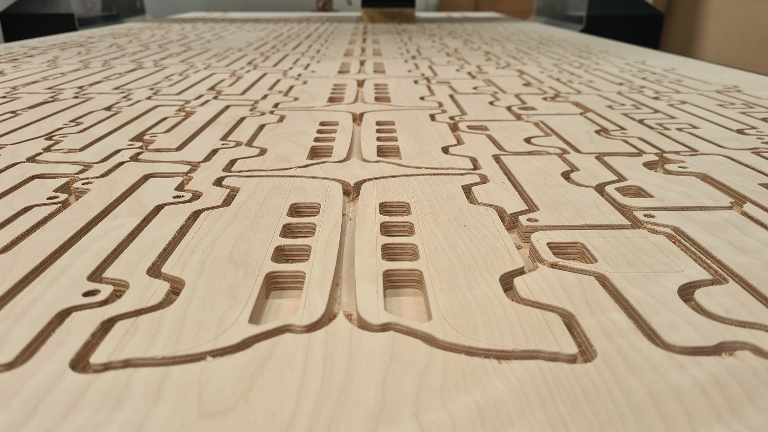
The component geometry, material, thickness, quantities and machining requirements have been confirmed. The project is ready to enter CNC production.
Williamstown CNC Works develops the CAM and machining strategy, selects the tooling, prepares the material and workholding, machines and monitors the job, then checks and organises the completed components at our Williamstown North workshop.
Not sure whether your files are ready? Visit Ready for Cutting.

CUT IT = Files to parts.
CUT IT MAY SUIT YOU IF
The Components Are Approved and Ready for CNC Production
Cut It begins once the component geometry, material, thickness, quantities, machining features and current revision have been approved.
Holes, Pockets and Rebates
The components require several controlled machining operations or depths rather than one simple through-cut.
Repeat Batches and Component Sets
Stable approved parts need to be produced as grouped quantities, matched sets or later unchanged orders.
Nested Sheet Components
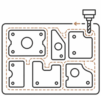
Multiple parts arranged across sheet material, with quantities, orientation, spacing, cutter access and reliable hold-down considered.
One-Offs and First Production Runs
Approved components are entering CNC production for the first time as a one-off, prototype or initial batch.
Profiles and Shaped Panels
Approved external and internal outlines need to be machined from sheet material, solid timber, plastics or suitable flat aluminium.
Detailed Parts and Fitted Features
Slots, tabs, joints, locating features or small details require suitable cutters, machining depths or test cutting.

Where dependable component geometry has not yet been produced, go to Draw It - CAD and File Preparation.
HOW CUT IT WORKS
From Approved Components to CNC-Machined Parts
Every CNC job requires production work before, during and after the machine is cutting. The exact process depends on the material, component geometry, quantities, machining operations and workholding required.


Confirm and Nest the Parts
We review the approved component geometry, quantities, material, thickness, orientation and current revision.
The parts are nested, or the supplied nest is checked, for spacing, cutter access, material support, grain or face direction and practical hold-down.

Develop the CAM Strategy
We select the required cutters and create the toolpaths for each profile, hole, pocket, rebate, engraving or suitable 3D operation.
The CAM determines machining depths, passes, entry movements, cutting direction, operation order, tool changes and part-retention methods.

Prepare, Machine and Monitor
The material is loaded, located and secured using the required vacuum zones, mechanical fixing or other workholding.
The cutters are loaded and measured, any agreed test cut is completed, and the job is machined while the operator monitors material movement, hold-down, dust, chips, heat, cutter condition and completed operations.

Clear, Check and Hand Over
The components and waste are unloaded, the CNC bed is cleared and the completed quantities and visible machining are checked.
Parts are then grouped for collection, agreed delivery or separately quoted Build It workshop services.
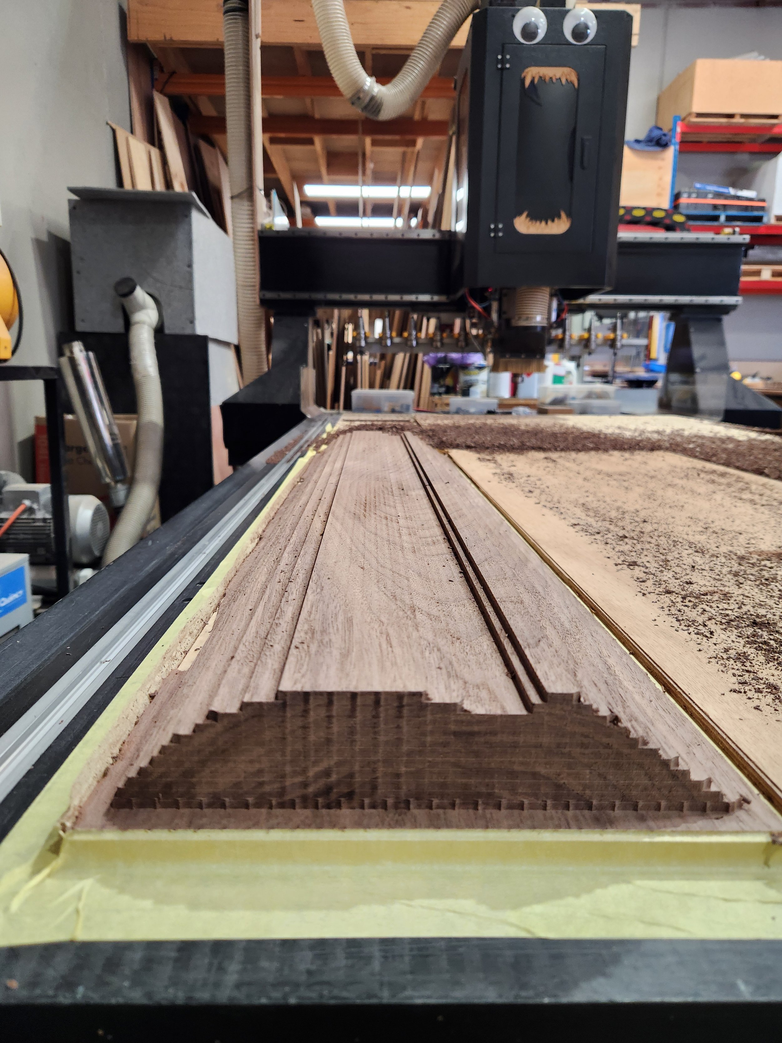
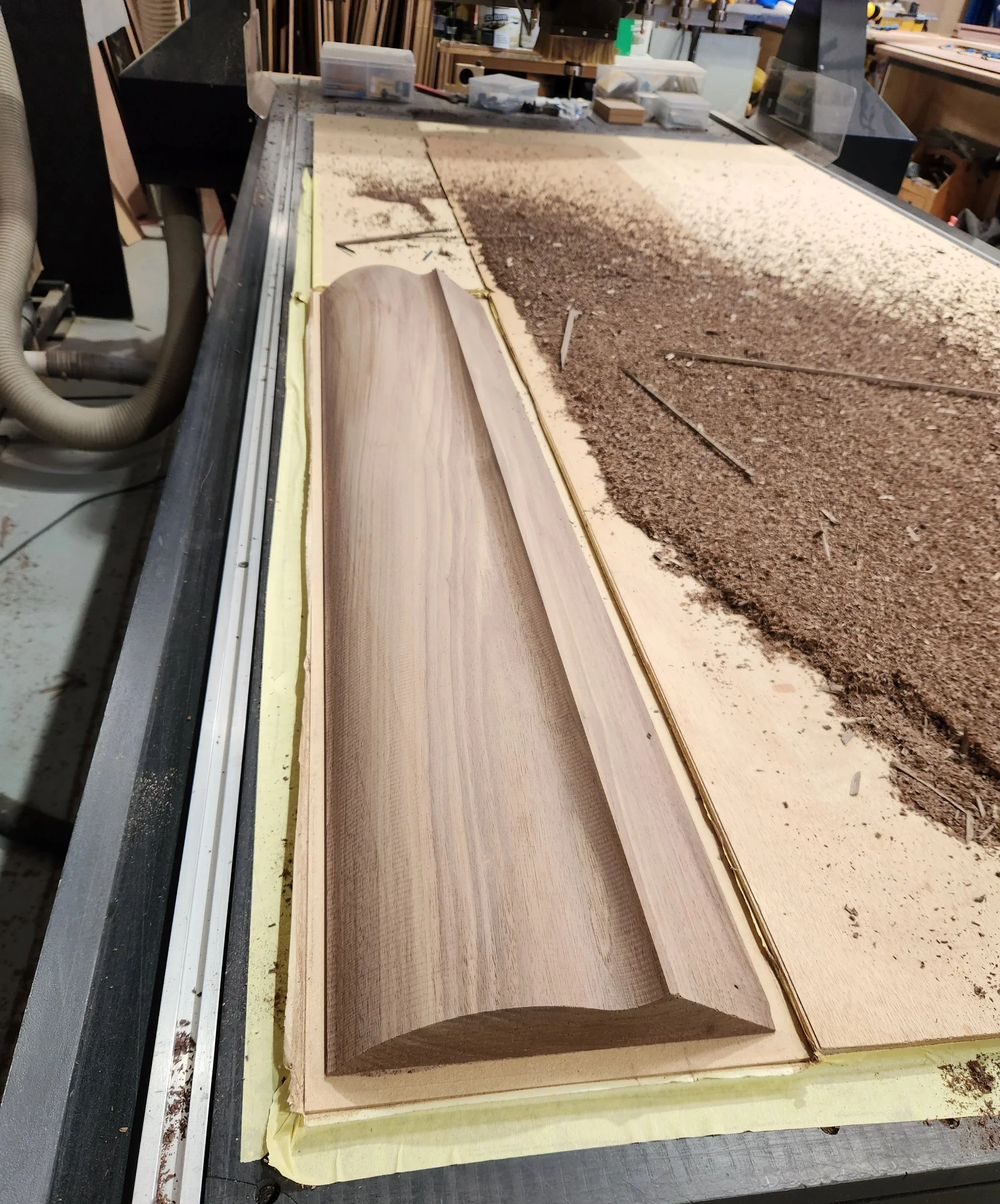
Cut It is not one fixed machining service.
A simple profile may require one cutter and a small number of operations. Another component may require several cutters, different machining depths, tool changes, detailed workholding and active checking between operations.
The quoted production scope may include:
reviewing the approved production information
checking or preparing the sheet nesting
CAM and CNC programming
cutter selection
profile cutting
holes and drilling operations
pockets and rebates
slots and locating features
engraving or component identification
chamfering
suitable 3D machining
cutter and tool changes
vacuum or mechanical hold-down
tabs, onion skin or other retention methods
agreed test cuts
machine and material setup
production monitoring
unloading, clearing and checking
grouping completed components
The required machining work and handover condition are confirmed before production proceeds.
A nested file still requires CAM, machine setup and monitored production before it becomes finished parts.
WHAT SHAPES THE PRODUCTION PLAN
The Material, Component and Production Setup all Affect Strategy
Approved geometry establishes what must be produced, but it does not create one universal cutting method.
The CAM, tooling, workholding and machining sequence must suit the actual material, component details and production requirements.
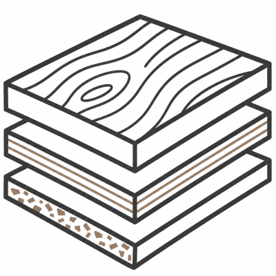
Material and Thickness
Different materials behave differently while they are being machined.
The production strategy may need to account for:
material type and grade
actual thickness
sheet flatness and condition
grain or face direction
dust and chip removal
heat build-up
edge or surface requirements
MDF, plywood, solid timber, plastics and suitable flat aluminium sheet do not use one identical cutting approach.
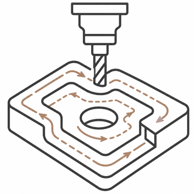
Component Geometry
The shape and detail of the component affect which cutters and machining operations can be used.
Important factors may include:
cutter access
internal corner radii
narrow slots
holes, pockets and rebates
varying machining depths
small or fragile details
fitted joints
machining from one or more faces
A detailed component may require several cutters, separate toolpaths and additional passes even when its overall size is small.
Workholding and Production Order
The material and individual components must remain secure while each operation is completed.
The production plan may need to consider:
vacuum coverage
mechanical fixing
tabs or other retention methods
spacing between parts
surrounding material support
the order of machining operations
tool changes
test cuts
first-component checking
unloading and grouping
The fastest-looking sequence is not always the safest or most reliable way to produce the parts.
Approved geometry defines the part. Material, component detail and workholding determine how it is machined.
BEFORE MACHINING
The Machining Strategy Must Suit the Material and Component
The component shape is only one part of preparing a CNC job.
The production method may also need to account for:
material type and grade
actual material thickness
sheet condition and flatness
grain or face direction
cutter diameter and access
internal cutter radii
pocket and rebate depths
narrow slots and small details
fitted joints
component size and shape
workholding
vacuum coverage
tabs or other retention methods
operation and cutting order
dust or chip removal
heat
cutter changes
test pieces
the required edge or surface result
Different materials require different approaches.
MDF creates large volumes of fine dust. Timber and plywood can splinter or move with the grain. Plastics can build heat or produce difficult chips. Suitable flat aluminium sheet requires appropriate tooling, lubrication or chip control, reliable hold-down and a strategy suited to the alloy and thickness.
Fitted parts may require a test cut using the actual material rather than relying only on nominal thickness.
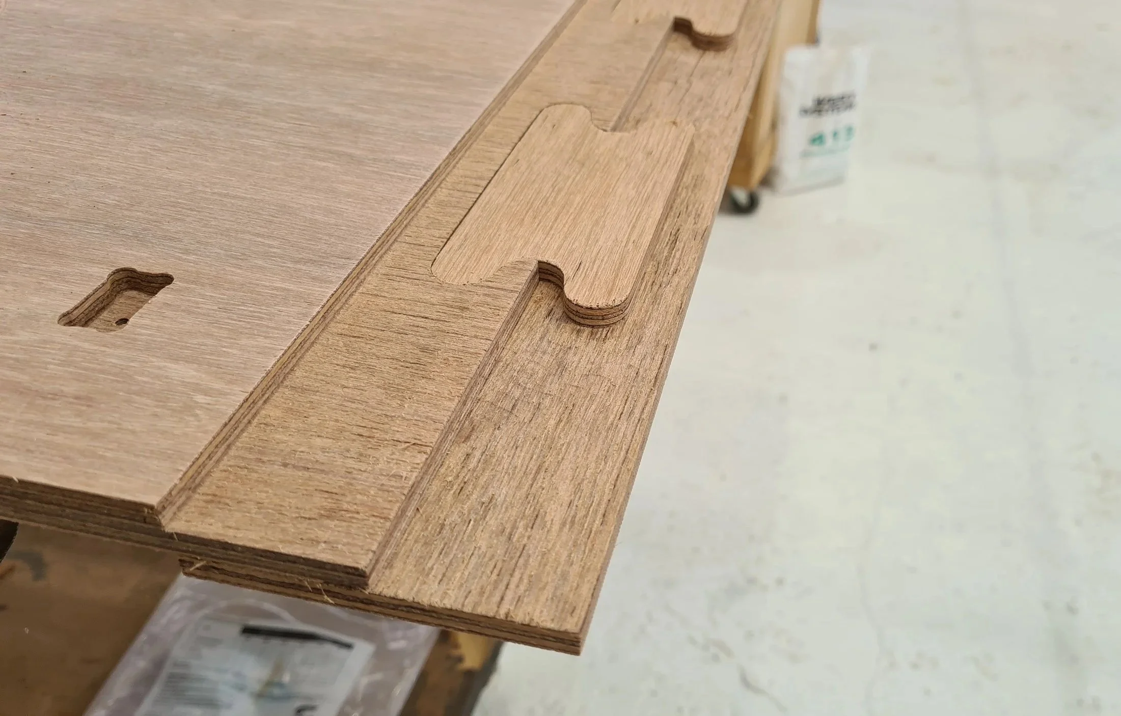
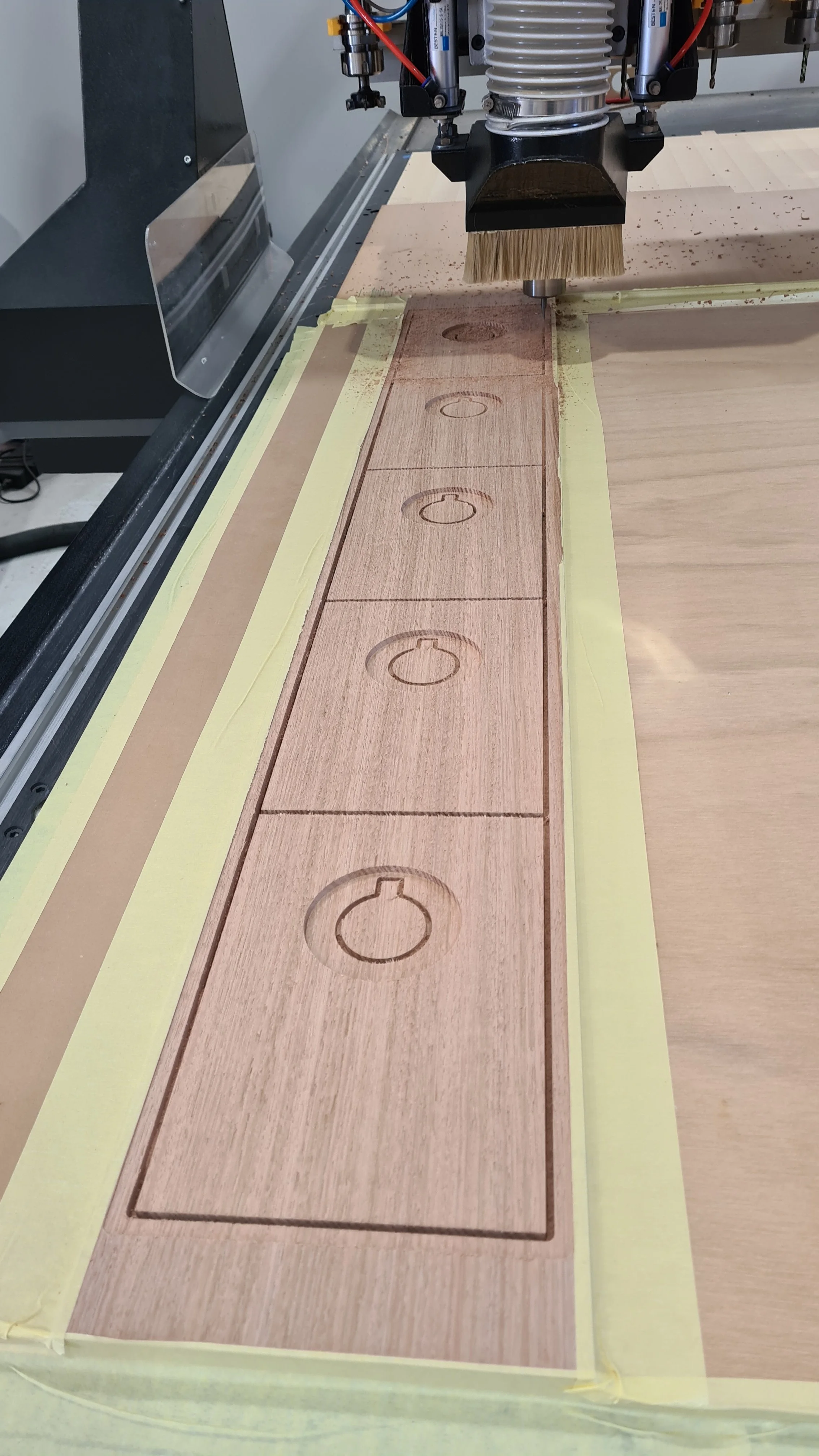
The machining strategy is developed around the actual component, material and production requirement rather than applying one universal cutting method.
CLEAR INPUTS AND APPROVALS
The Parts Are Approved Before Production

Production Approved
Before Cut It begins, the approved production information identifies:
current component geometry
material and thickness
quantities
machining features and depths
grain, face or orientation requirements
handed and mirrored parts
important fit requirements
the current revision
For detailed submission requirements and accepted starting files, Visit Ready for Cutting.
We Determine
Williamstown CNC Works determines:
nesting and CAM strategy
cutter selection
toolpaths
cutting depths and passes
entry and exit movements
cutting and tool-change order
workholding
part-retention methods
machine setup
production monitoring
practical unloading and checking
These decisions are based on the approved components and agreed production scope.
You Approve
Before production begins, you approve:
component shapes
critical dimensions
material and thickness
quantities
holes, pockets and rebates
machining depths
grain or face direction
handed or mirrored components
important fit requirements
the current revision
the intended use
The customer remains responsible for approving the component design, dimensions, quantity and intended use.

Quoted Separately
Unless specifically included, Cut It does not automatically include:
project development or CAD changes
material supply
prototypes or test pieces
sanding, laminating, edgebanding, assembly or finishing
packaging, delivery, installation or site work
engineering, certification or regulatory approval
WCW’s CAM files, toolpaths and internal machine settings are not included unless agreed.
Anything outside the approved production scope is quoted separately.
UNDERSTANDING CUT IT
The Work Depends on the Component, Material and Machining Required
Two components can look similar while requiring very different amounts of programming, setup and machine time.
One may be a large profile produced with a single cutter and a small number of passes. Another may require several cutters, small internal details, pockets, rebates, tool changes and closer monitoring throughout the job.
The amount of production work may be affected by:
material and thickness
number of components
sheet nesting
cutter diameter and access
internal details
machining depths
number of operations
tool changes
workholding
component size and shape
tabs or other retention methods
cutting order
dust, chips or heat
test cutting
unloading and sorting requirements
required handover condition
A simple-looking file can therefore require a carefully planned machining strategy.
The purpose is not only to make the router move around an outline. It is to establish a practical production method for the actual material, geometry and required result.

"The machine follows the instructions. It does not make the production decisions."
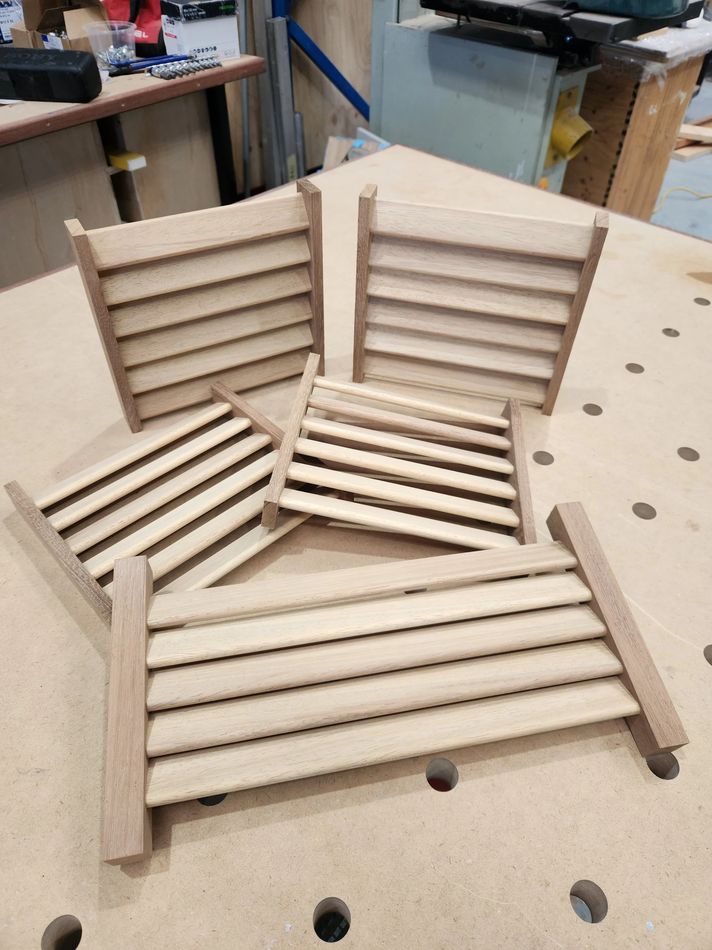
Every CNC job requires CAM, setup, workholding and monitoring before approved geometry becomes finished parts.
PRODUCTION WORK
How Different Components Enter CNC Production
Approved components can require very different machining strategies.
The material, quantity, geometry, operations and workholding determine how each job is nested, programmed, set up and monitored.
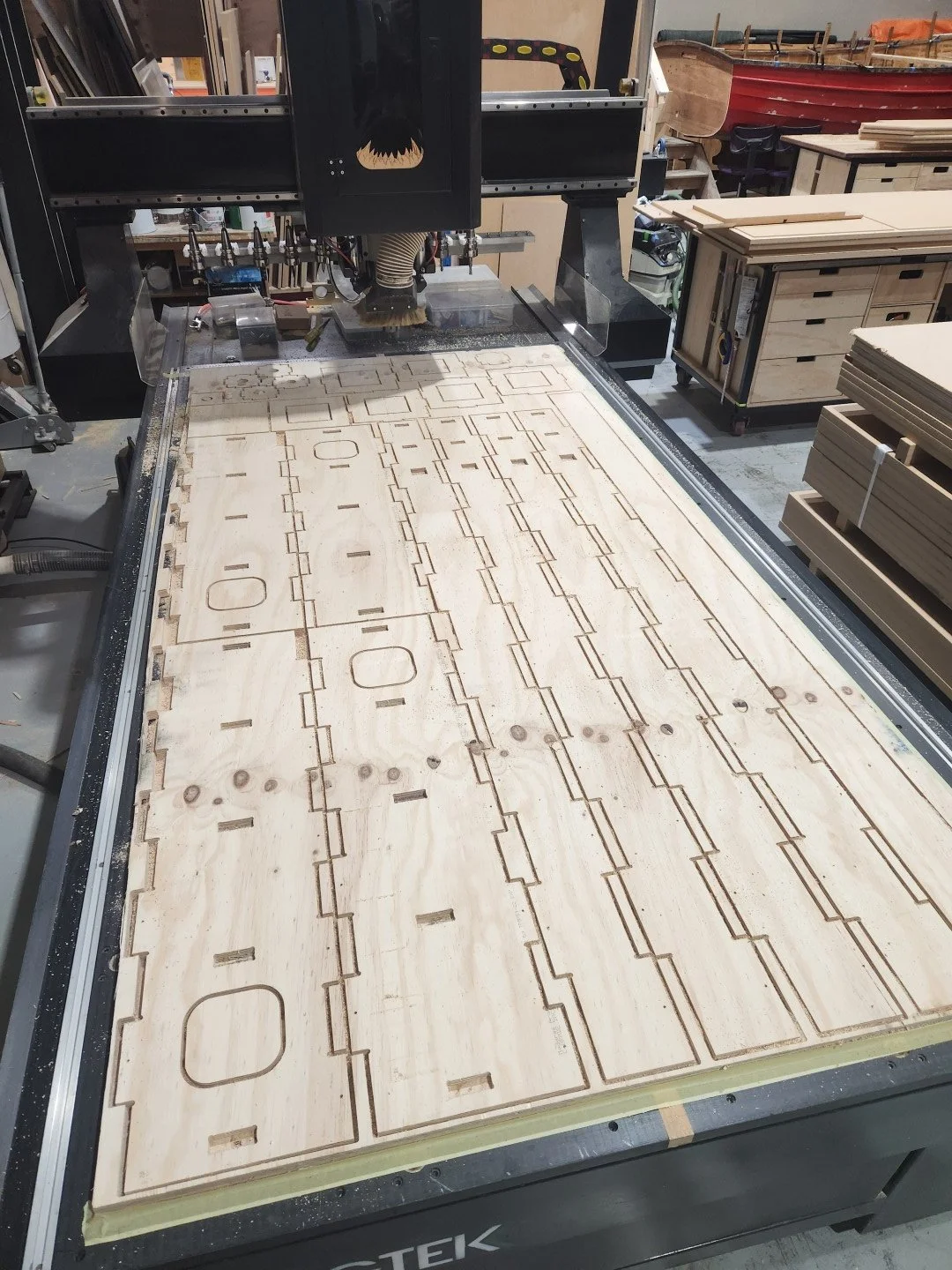
Nested Sheet Production
Nesting arranges multiple components across a sheet or piece of material before machining.
A production nest may need to account for:
component quantities
material size
grain or face direction
handed or mirrored parts
spacing between components
cutter access
workholding
component identification
cutting order
material yield
The tightest possible arrangement is not always the safest or most efficient machining layout.
Parts placed too closely together may reduce vacuum hold-down, leave insufficient material support or make it difficult to retain smaller components after surrounding material has been removed.
A supplied nested file still requires production review and CAM before machining.
Profile and Panel Cutting
Profile cutting produces the external or internal outline of an approved component.
This may include:
shaped panels
templates
curved formers
solid timber components
plastic parts
suitable flat aluminium parts
internal openings
repeated profiles
The cutter must suit the material, thickness, required detail and desired result.
A larger cutter can often machine more efficiently but cannot reach tight internal details. A smaller cutter can follow finer geometry but may require shallower passes and more machine time.
Internal corners retain the radius of the cutter unless suitable reliefs or another agreed machining method are included in the component geometry.

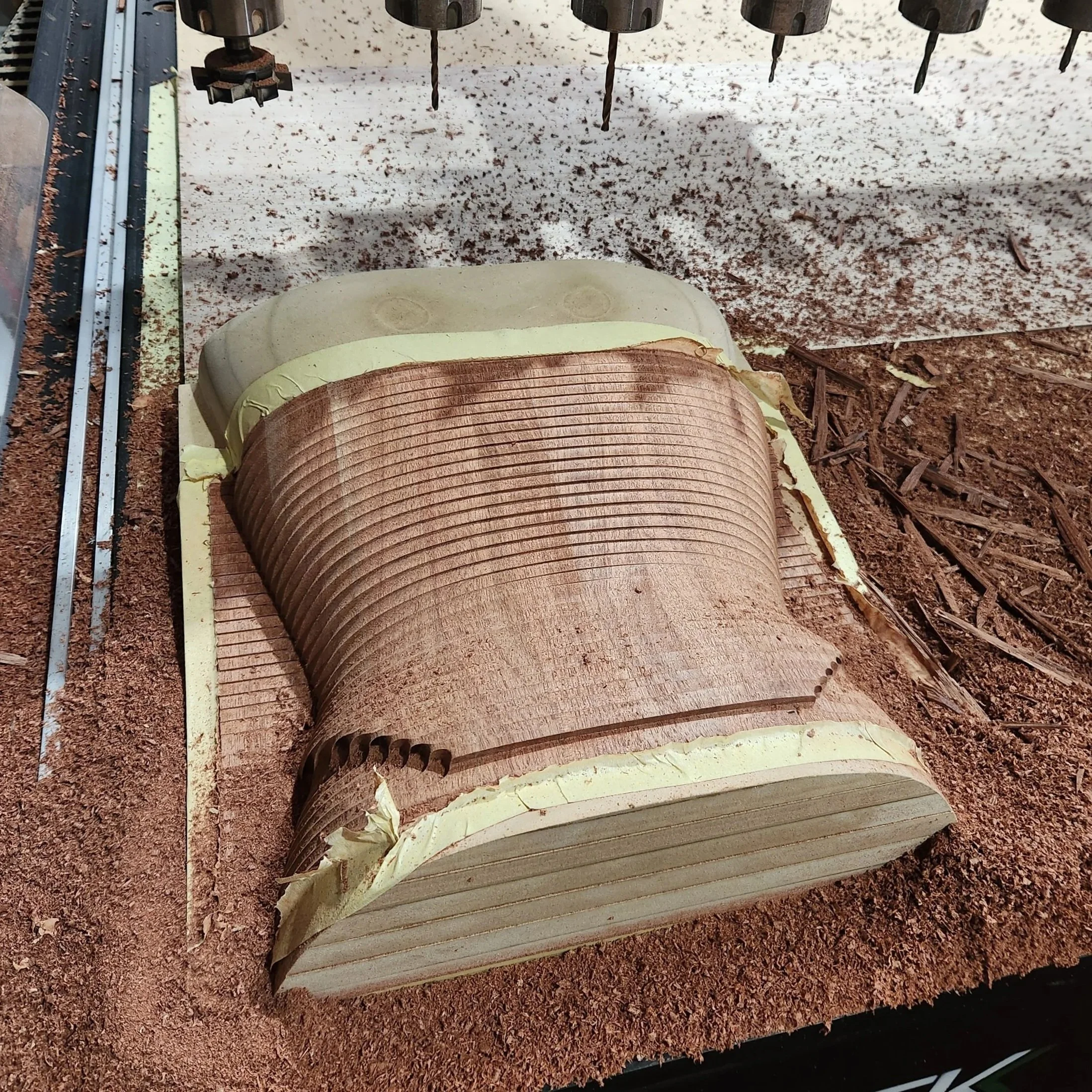
Multi-Operation Components
A component may require several machining operations before it is complete.
These can include:
external profiles
internal cut-outs
through-holes
drilled positions
pockets
rebates
slots
engraved identification
chamfers
varying-depth features
suitable 3D machining
Each operation may require a separate toolpath, depth, cutter or machining strategy.
Pockets, holes and internal features are often completed before the outside profile so the component remains supported while the detail is machined.
The operation order must account for the material that will remain after each stage.
Detailed and Fitted Parts
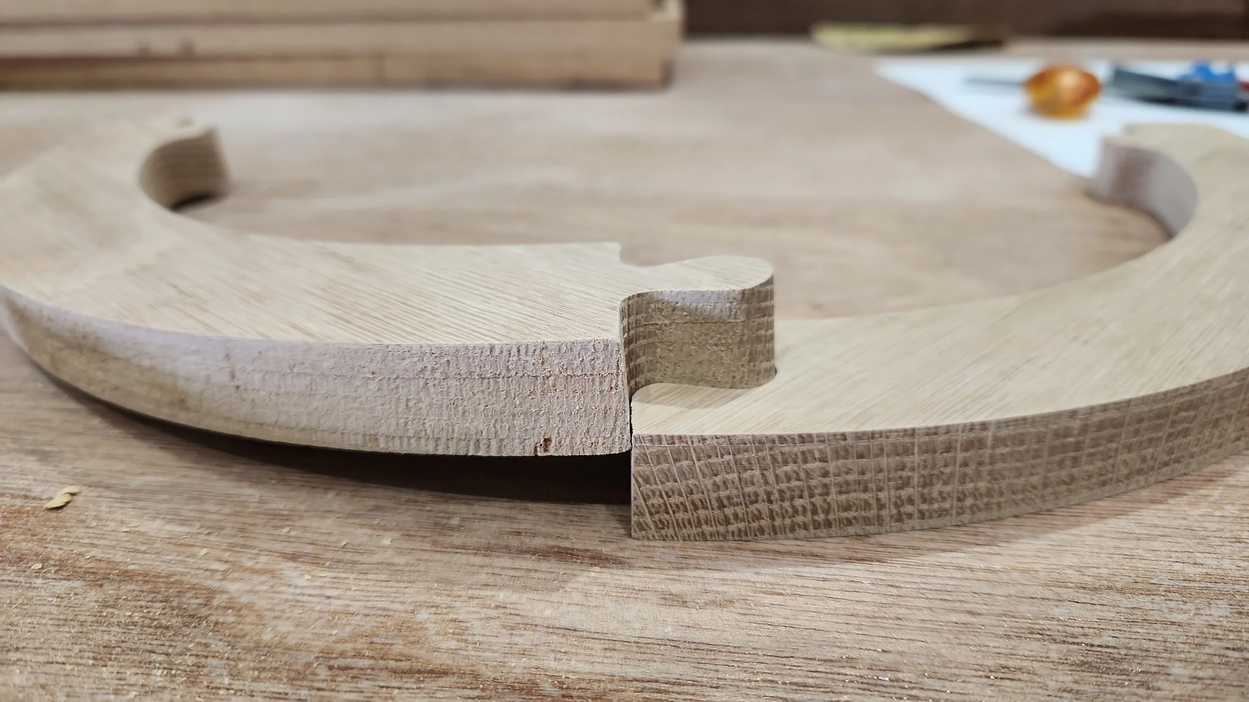
Slots, tabs, joints, locating features and small internal details may require closer control than a simple profile.
The machining method may be affected by:
actual material thickness
cutter radius
narrow slots
deep pockets
small internal features
joint clearance
machining face
component orientation
required fit
Nominal sheet thickness is not always the exact thickness of the delivered material.
Where a result depends on a fitted joint or critical detail, a test component may be recommended using the actual material.
The customer approves the required fit. Williamstown CNC Works prepares the machining method and produces any agreed test piece before the complete run proceeds.
First Production Runs
A first production run establishes how an approved component performs in the selected material and machining process.
It may be used to confirm:
material behaviour
cutter and machining strategy
workholding
component identification
important dimensions or fitted details
unloading and handling
the practical result before repeat quantities
Where an approval point is required, the first component or initial batch can be checked before later production proceeds.
Changes identified after the approved first run may require updated geometry, CAM or production setup.
Repeat Production
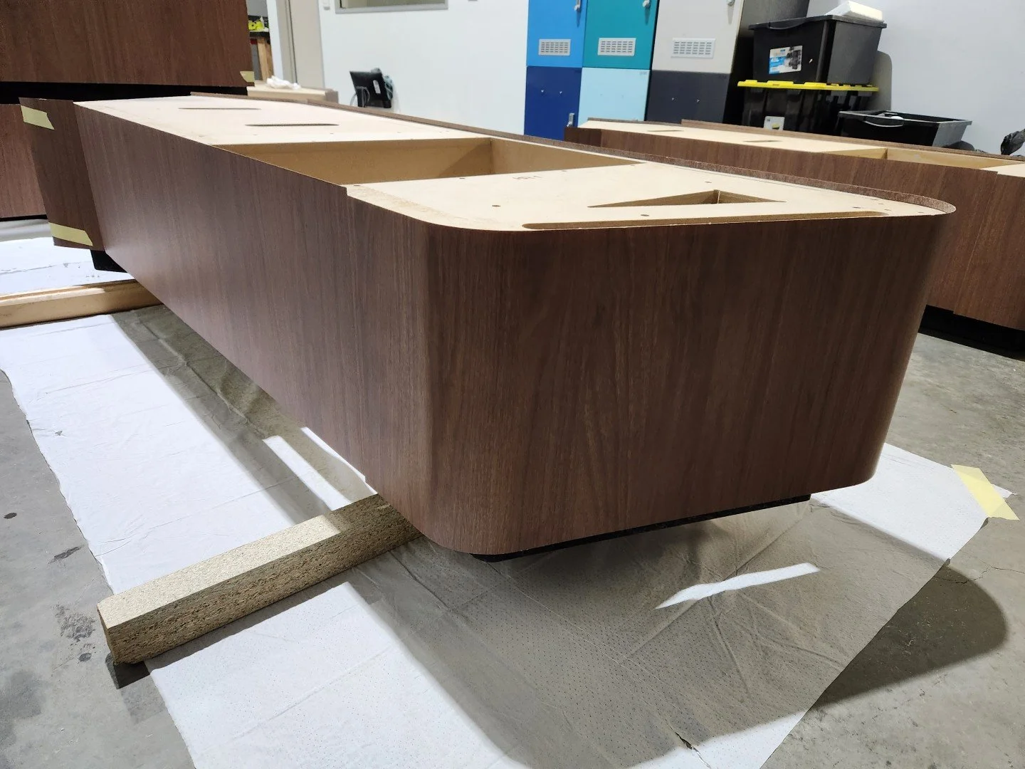
Stable approved components can be produced as grouped quantities, matched sets or later repeat orders.
Repeat production works best when the customer clearly identifies:
current component names
quantity of each component
handed and mirrored parts
approved revision
material and thickness
any change from the previous order
Where the component geometry, material and machining requirements remain unchanged, existing production information may reduce avoidable setup and review work.
Each repeat order is still checked against current quantities, material availability and production requirements before machining.
Changes should be identified before the repeat run is authorised.
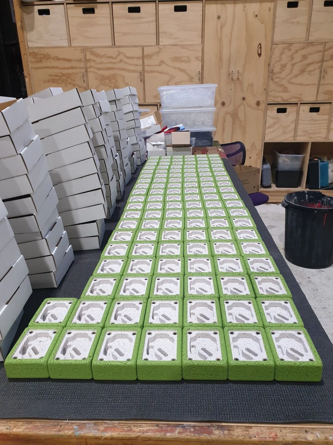
Each production job begins with approved component information, but the CAM, tooling, setup and monitoring depend on the actual work being produced.
Where dependable component geometry does not yet exist, go to Draw It - CAD and File Preparation.
THE NEXT PRODUCTION STAGE
Move Forward When the Project Is Ready

Go To DREAM IT
Choose Dream It when important decisions about the project, construction, dimensions or intended result remain unclear.
Go to DREAM IT - Project Creation
Go to DRAW IT
Choose Draw It when the project direction is understood but dependable CNC component files still need to be created, redrawn or repaired.
Go to DRAW IT - CAD & File Preparation
Add BUILD IT
Choose Build It when the CNC-cut components also require agreed workshop work such as laminating, sanding, edgebanding, trial assembly or finishing.
Go To BUILD IT - Additional Services
Some projects may only require one stage. Others may move through Dream, Draw, Cut and Build as separate quoted parts of the same project.
RELATED PROJECT PATHWAYS
Start With Your Project Type
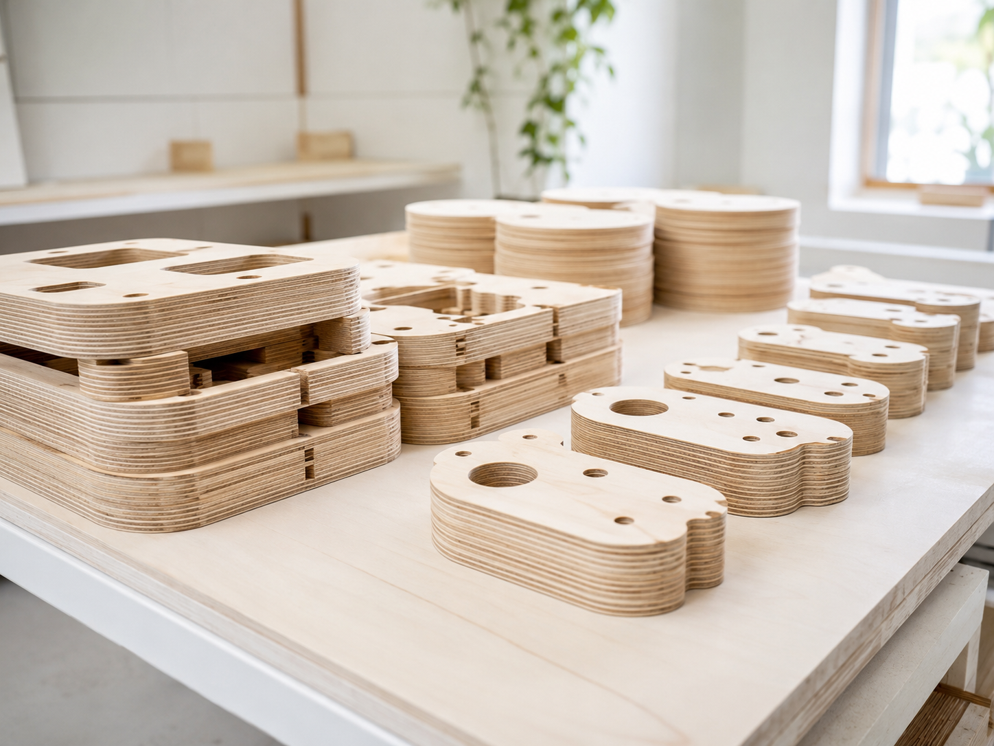
Small-Batch Production - First runs, repeat batches and controlled production parts.
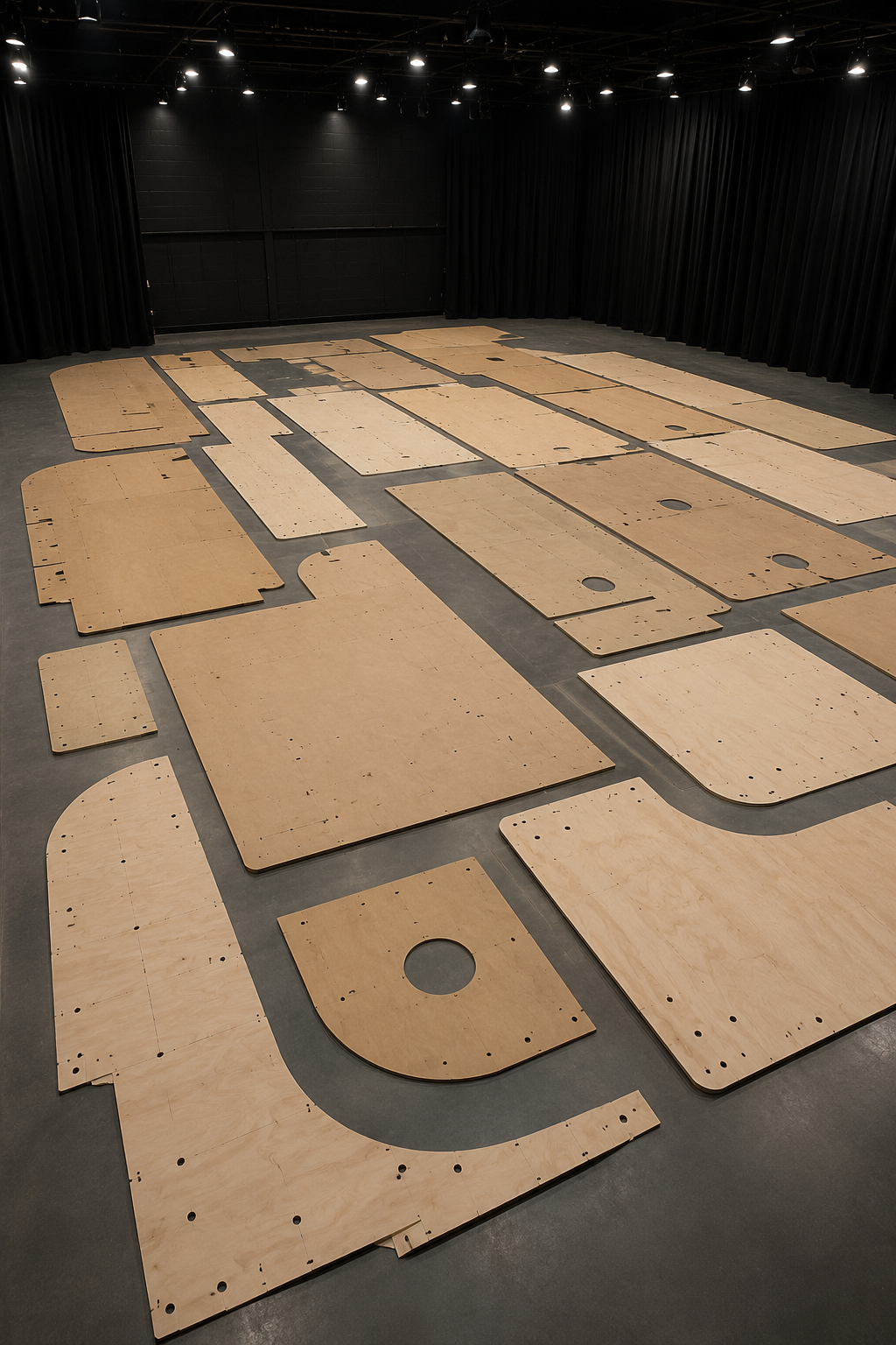
Templates and Patterns - Reusable guides, patterns and workshop templates.
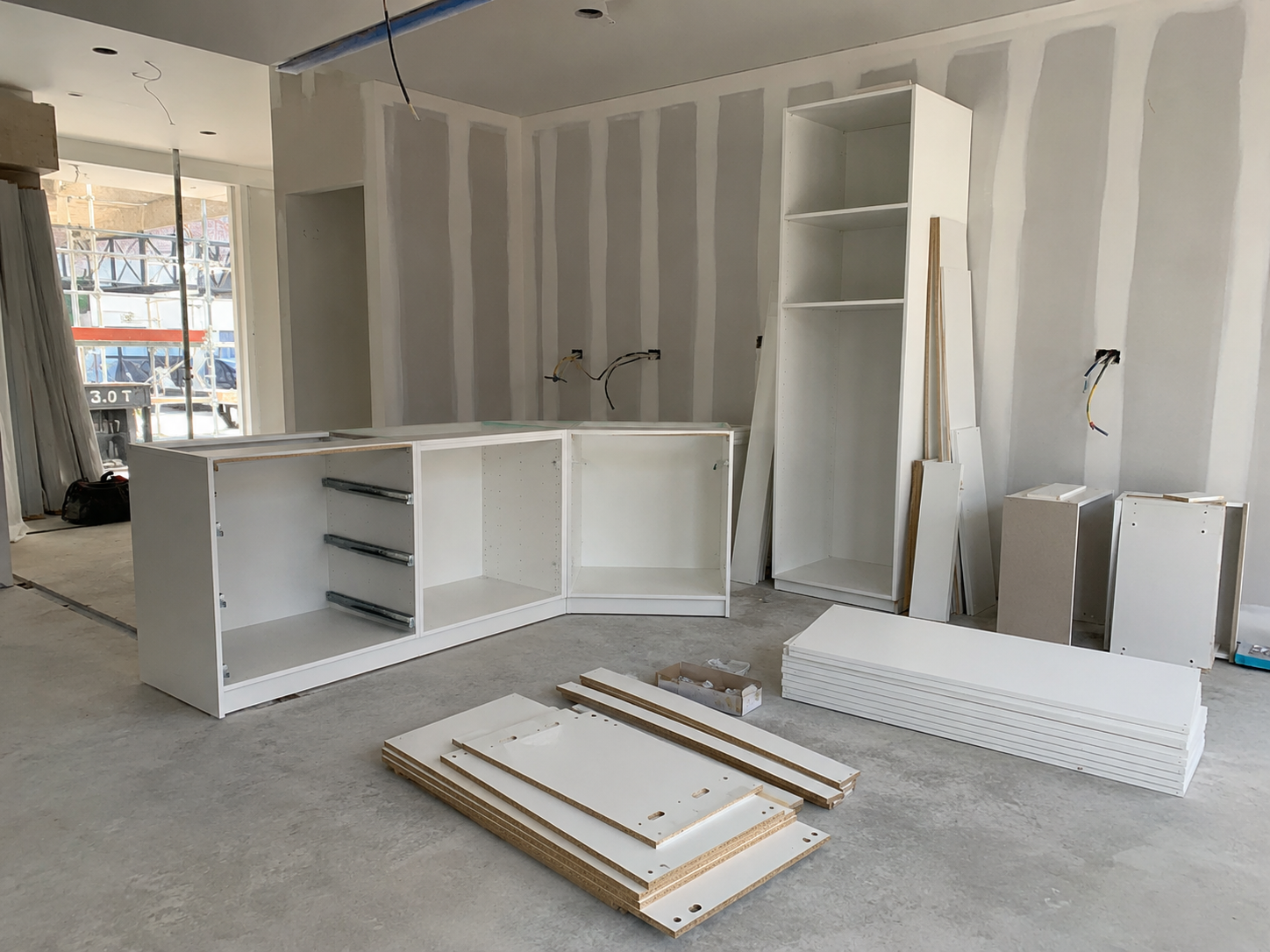
Construction and Trade - Panels, formers, fitout parts and CNC-cut trade components.

Designers & Custom Projects - Defined custom products, specialist one-off components.
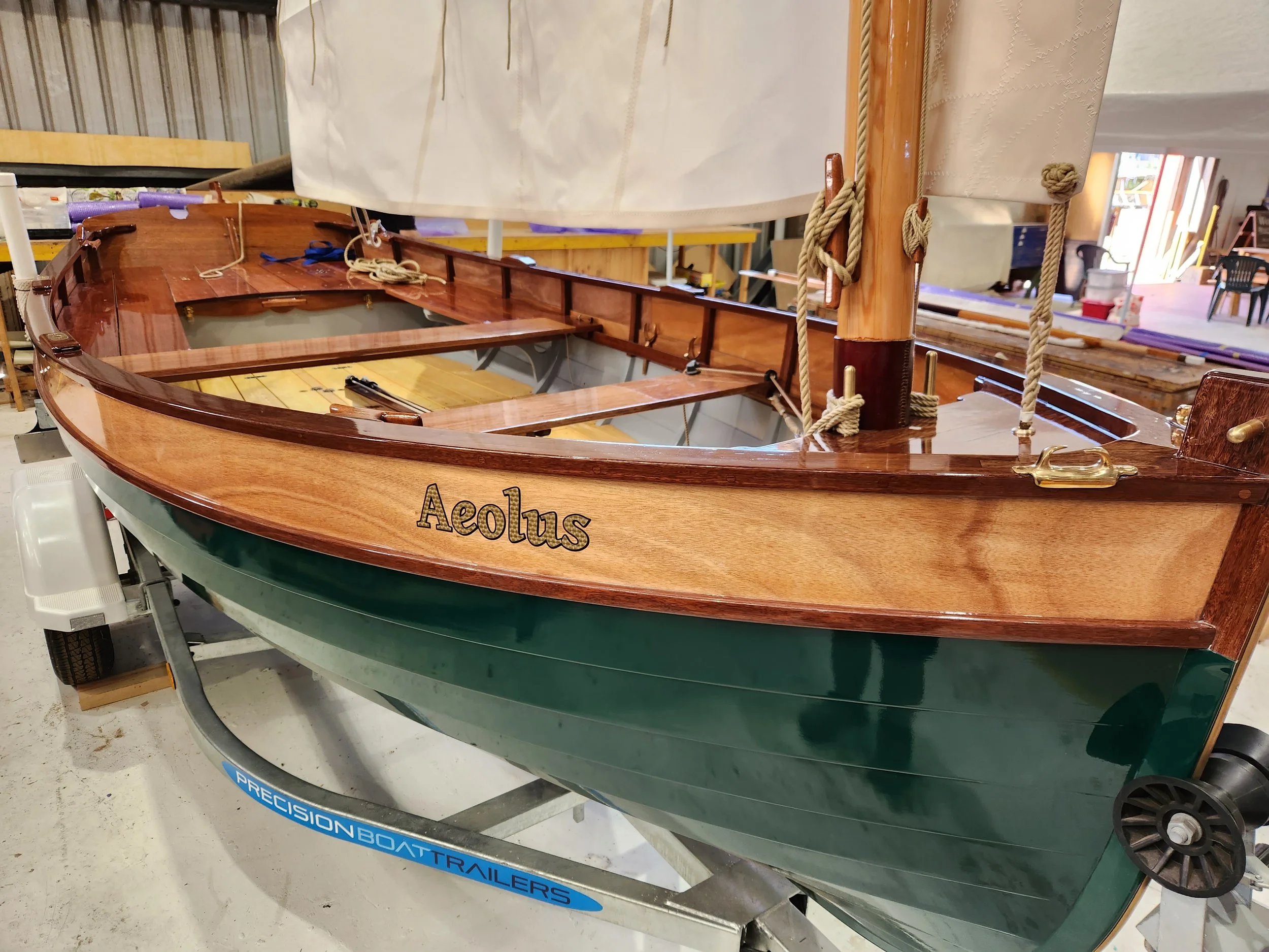
Boatbuilding and Marine - CNC-cut marine parts, patterns and fitout components.
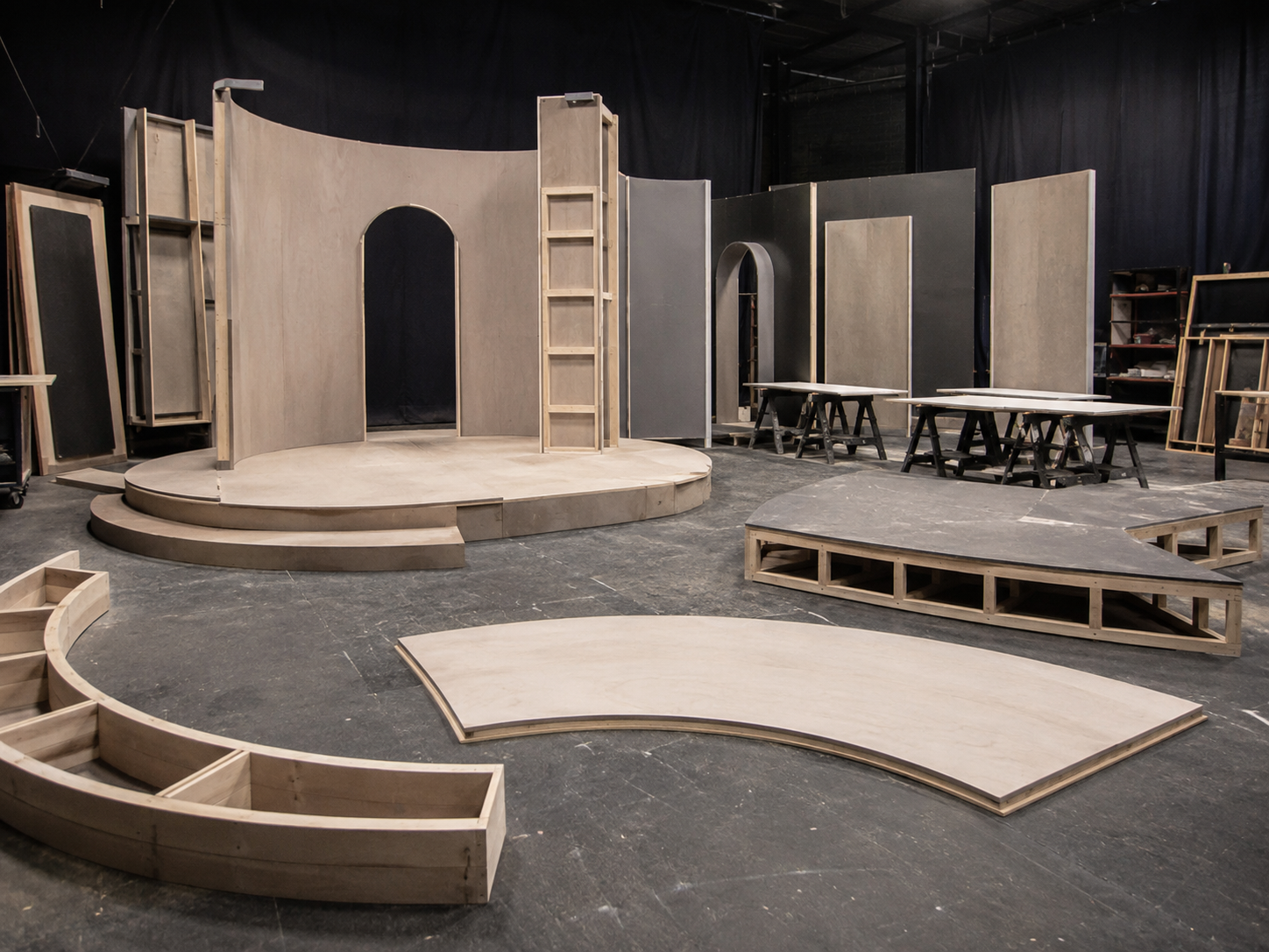
Set, exhibition and fabrication parts - CNC-cut parts for sets, displays and temporary builds.
Cut It Frequently Asked Questions
-
CAD means Computer-Aided Design. It contains the approved geometry defining the components.
CAM means Computer-Aided Manufacturing. It converts the approved geometry into toolpaths and machining instructions.
CNC means Computer Numerical Control. The CNC router performs the programmed movements.
In plain language:
CAD defines the component
CAM defines how it will be machined
CNC performs the programmed work
-
A toolpath is the programmed route followed by the cutter.
It can define the machining depth, number of passes, entry and exit movements, cutting direction, operation order, tool changes and tabs or other retention methods.
One component may require several separate toolpaths.
-
Nesting is the arrangement of components across a sheet or piece of material before machining.
A production nest may consider quantities, sheet size, grain or face direction, spacing, cutter access, workholding and material use.
A supplied nest is still reviewed and requires CAM before machining.
-
Profile cutting follows the inside or outside outline of a component.
Pocketing removes material from a controlled area without cutting through the full thickness.
Drilling or hole machining produces holes at defined locations and sizes.
Engraving produces shallow text, marks or identification details.
Chamfering creates an angled edge using suitable tooling.
3D milling produces suitable curved or varying-depth surfaces using toolpaths that move through several levels.
One component may require several of these operations.
-
Feed rate is how quickly the cutter moves through the material.
Spindle speed is how quickly the cutter rotates.
Pass depth is the amount of material removed during one machining level.
These settings are selected around the material, cutter, depth, component geometry, workholding, chip removal and required result.
There is no single setting that suits every cutter and material.
-
Workholding is the method used to keep the material and individual components flat, stable and secure during machining.
Depending on the job, this may involve:
vacuum hold-down
mechanical fixing
tabs
surrounding material
a planned cutting order
additional support
Vacuum performance changes as material is removed and depends on the sheet size, material condition and exposed bed area.
-
Tabs are small sections of material intentionally left between a component and the surrounding sheet.
They can help prevent small or difficult components from moving after most of their outside profile has been machined.
Tabs are removed after machining and are not required on every job.
-
Every machining operation removes material and may reduce the support or hold-down remaining around the components.
Pockets and internal details may be completed before the outside profile. Smaller components may be cut later, and some areas may remain connected temporarily.
The safest production sequence is not always the shortest-looking sequence.
-
The component geometry may remain unchanged while the production method changes.
Different CAM may be required when the material, thickness, cutter, quantity, sheet size, workholding, machining depth or required finish changes.
A plywood, plastic and flat aluminium component should not be assumed to use the same tooling or machine settings because the geometry is identical.
-
The cutter is selected around the material, thickness, component geometry, machining depth and required result.
Larger cutters can often remove material more efficiently but cannot reach very tight internal details.
Smaller cutters can follow finer geometry but generally require shallower passes and more machine time.
The smallest cutter that fits the drawing is not automatically the best cutter for the whole job.
-
A test cut may be recommended where the result depends on:
actual material thickness
slot or tab fit
cutter radius
pocket depth
material behaviour
workholding
a critical assembly detail
a new machining method
Required test cutting is identified and quoted separately.
-
No.
The router follows the prepared toolpaths, but the operator monitors the material, hold-down, dust, chips, heat, cutter and completed operations.
A job may need to be paused if material movement, chip build-up, heat or another production issue develops.
-
The outside outline is only one part of the job.
Time may also be required for:
production review
nesting
CAM
cutter selection
tool changes
multiple machining depths
workholding
test cutting
monitoring
unloading
clearing the machine
checking and grouping components
A simple-looking component may also be repeated many times.
-
Not automatically.
Cut It supplies the agreed CNC-machined components.
Sanding, laminating, edgebanding, assembly, finishing and other suitable workshop work can be considered separately through Build It.
-
Provide the current component names, revision, material, thickness and required quantities.
Where the geometry and production requirements remain unchanged, existing production information may be used as the starting point for the repeat quote.
Any changes must be identified before the new run is authorised.