
DRAW IT
CAD, Redrawing and CNC File Preparation
You have plans, drawings, a model, existing CAD, measured information or a physical reference, but the components are not yet ready for dependable CNC production.
Williamstown CNC Works can review the information, redraw or repair the required geometry and prepare an agreed production file for accurate machining.
Still working from an idea or rough concept? Start with Dream It.
Start with the stage that best matches the information you have now. Not every project needs all four stages.
DREAM IT
I have an idea or rough concept.

DREAM IT

DRAW IT
CUT IT
BUILD IT
CUT IT
I have production-ready files.
DRAW IT
I have drawings, plans or a model.
BUILD IT
I need parts plus workshop work.
YOUR STARTING POINT
Drawings and Models Still Need to Define the Parts
A plan, PDF, sketch or 3D model can provide useful project information without being ready to send directly to the CNC router. The required components may still need to be identified, redrawn, checked, separated or adjusted for the selected material and machining process.
Existing files can also contain:
Open or duplicated geometry
Missing dimensions
Inconsistent scale
Overlapping lines
Parts that have not been separated
Details that cannot be produced with the intended cutter
Information intended for reference rather than machining
Several revisions with no clearly approved version
Draw It is the stage where reliable project information is converted into approved CNC component geometry.
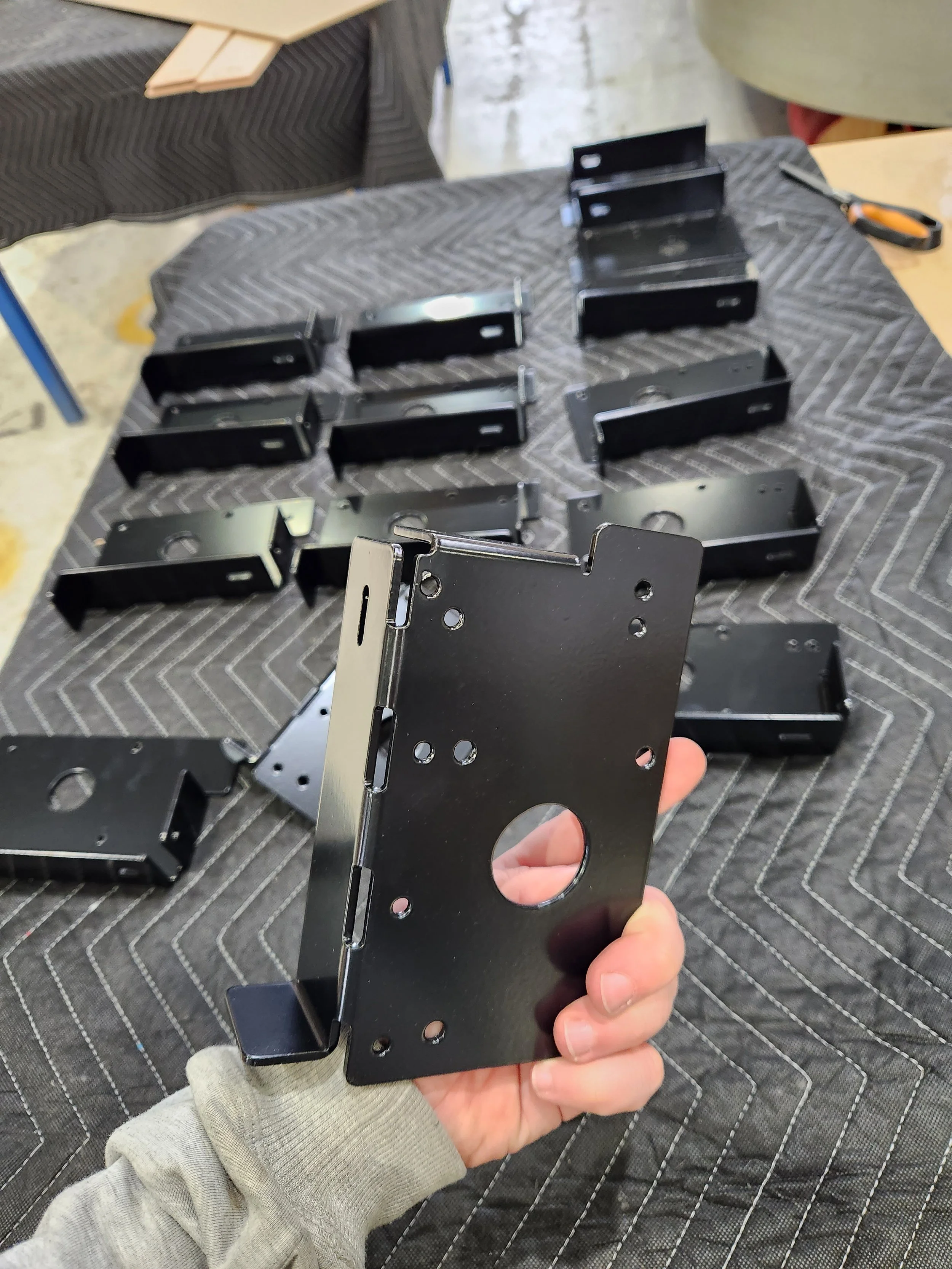

A file that opens successfully is not automatically a production-ready CNC file.
DRAW IT MAY SUIT YOU IF
The Project Is Understood, but the Cutting Information Is Not Yet Complete
I Have Existing CAD Files
The files may be substantially complete but require checking, cleanup, repair, component separation or production preparation.

My Files Need Adjusting for CNC
The parts exist, but cutter radii, fitted joints, holes, pockets, rebates, layers or other machining details still need to be resolved.

I Have Dimensioned Drawings or Plans
The project is shown clearly, but the individual components still need to be extracted or redrawn for CNC production.

I Have a Physical Pattern or Part
The shape needs to be measured, traced, digitised or interpreted before a dependable cutting file can be created.
I Have a PDF or Marked-Up Sketch
The dimensions and intended result are dependable enough to work from, but there is no usable component geometry.
I Have a 3D Model
The overall model exists, but the individual sheet components, machining details or material thicknesses have not been prepared.
HOW THIS STAGE WORKS
Turning Reliable Project Information Into CNC-Ready Components
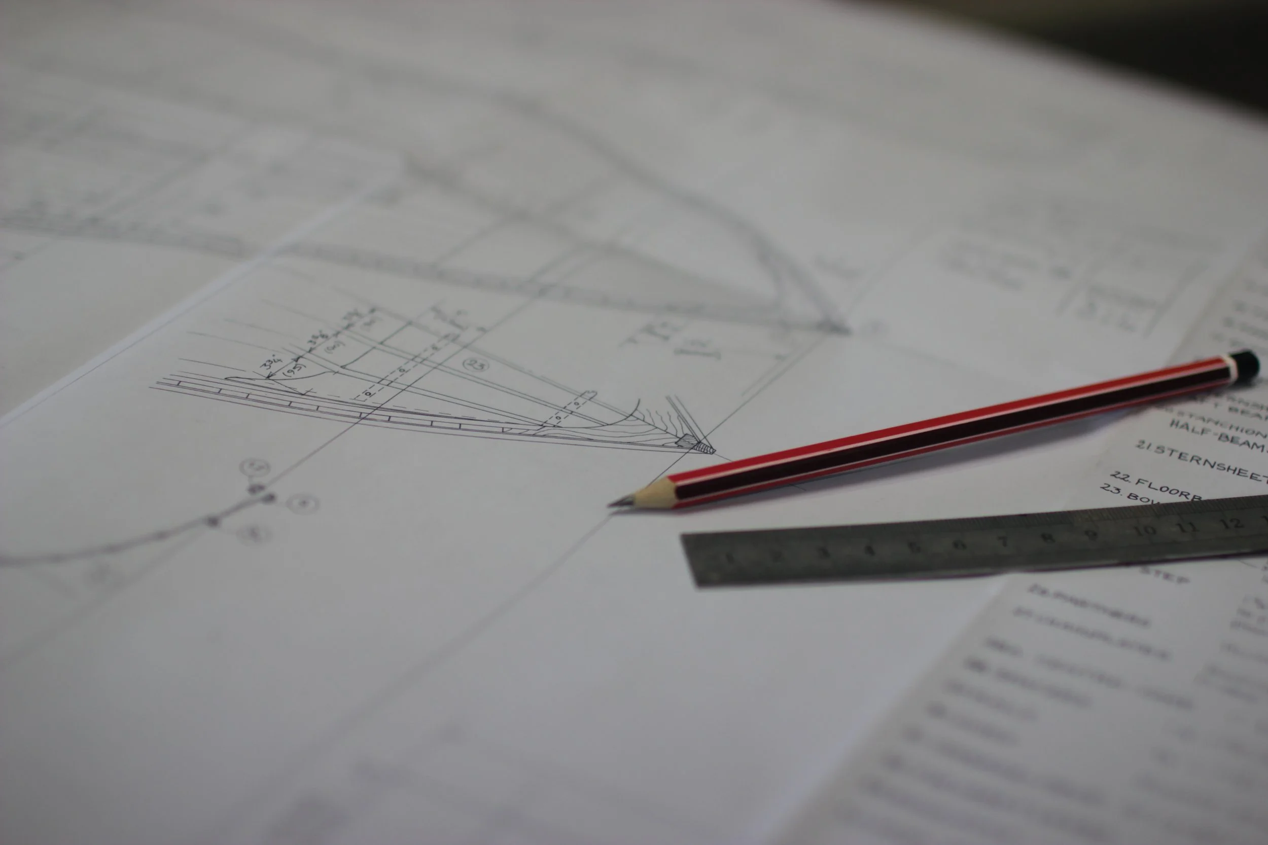
1 - You Bring
Provide the most dependable information currently available, such as:
Dimensioned drawings
Plans or PDFs
Existing CAD files
2D or 3D models
Measured sketches
Physical patterns or components
Material and thickness
Quantities
Required machining details
Photographs or assembly references
Clearly identify which information is approved, which is approximate and which decisions are still outstanding.
2 - Williamstown CNC Works Develops
Depending on the agreed scope, we can:
Review the supplied information
Confirm the intended components
Check scale and critical dimensions
Redraw missing or unsuitable geometry
Repair or simplify existing files
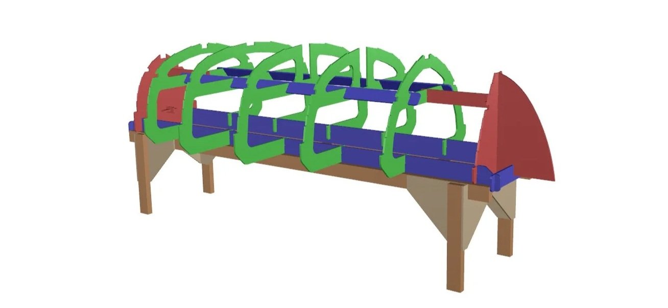
Separate parts from larger drawings or models
Add agreed holes, pockets, rebates or profiles
Consider practical cutter access and internal radii
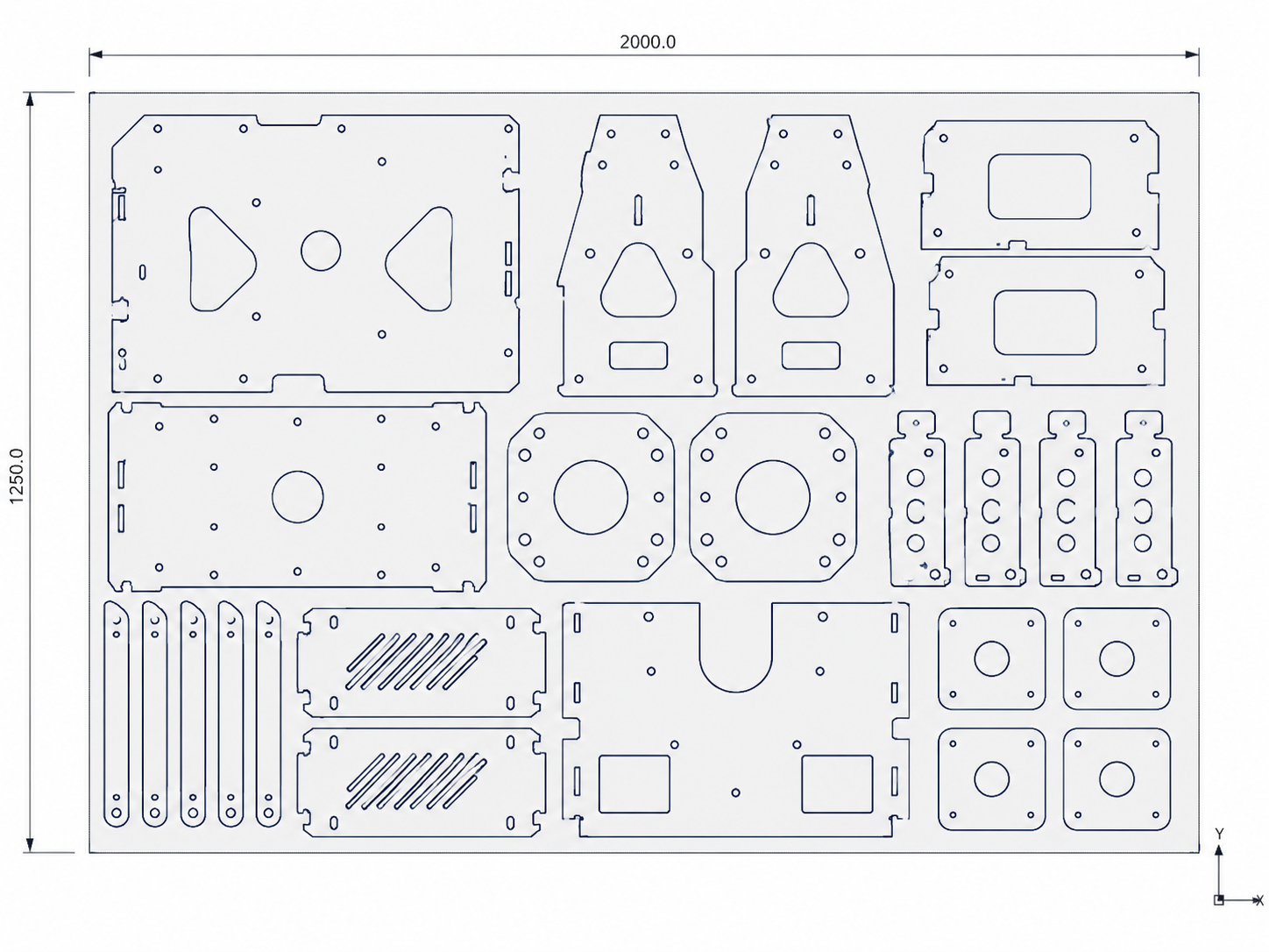
Organise geometry for CNC programming
Prepare an approval version before machining
3 - You Approve
Before cutting begins, you review the agreed production information and confirm:
Component shapes
Critical dimensions
Material
Thickness
Quantities
Machining requirements
Relevant handed or mirrored parts
The approved revision
Once the required information is approved, the project can move into Cut It.
POSSIBLE STARTING FILES
Different Projects Arrive in Different Forms
3D Models
A model can help explain the complete project, but individual components may still need to be extracted, flattened, separated and adjusted for the real material.
Existing 2D CAD
DXF, DWG or other vector geometry may only require checking and cleanup, or it may need more substantial repair and interpretation.
Dimensioned Plans and Drawings
Architectural drawings, workshop drawings, fabrication drawings and marked-up plans can provide the basis for redrawing when the relevant dimensions are clear.
Physical Patterns and Existing Parts
Existing objects can sometimes be measured or digitised.
The condition, size, shape and required accuracy of the reference affect the time and method required.
PDF Files
PDFs can be useful references, but imported lines are not always suitable production geometry.
Scale, dimensions and the intended components must still be checked.
Sketches and Measurements
Measured sketches may be suitable where they clearly define the required shape and critical dimensions. Rough concept sketches without dependable measurements may need to begin under Dream It instead.
Reference images are useful for understanding the intended result, but photographs alone do not define accurate component geometry.
DRAW IT SERVICES
Preparing the Information Needed for Production
Redrawing From Plans - Creating clean component geometry from suitable dimensioned drawings, PDFs or measured information.
CAD Cleanup and Repair - Removing duplicate lines, joining open curves, correcting obvious file faults and preparing usable geometry from supplied CAD.
Component Extraction - Separating individual panels, profiles, templates or parts from a larger drawing or model.
Production Geometry - Preparing the profiles, holes, pockets, rebates and other agreed details required for CNC machining.
Existing Part Reproduction - Measuring or interpreting suitable physical references to create replacement or modified component geometry.
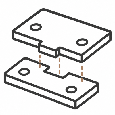
Joint and Fit Preparation - Preparing tabs, slots, rebates or locating features around the confirmed material thickness and intended assembly method. Test cuts may be required before a fitted detail is approved.
Revisions and Approval Files - Producing clearly identified versions so the customer can review the relevant geometry before production.
Repeat Production Preparation - Organising stable component information so an approved job can be quoted and produced again with fewer unresolved decisions.
DRAW IT SERVICES
Several Steps May Sit Between a Drawing and a Cut Part
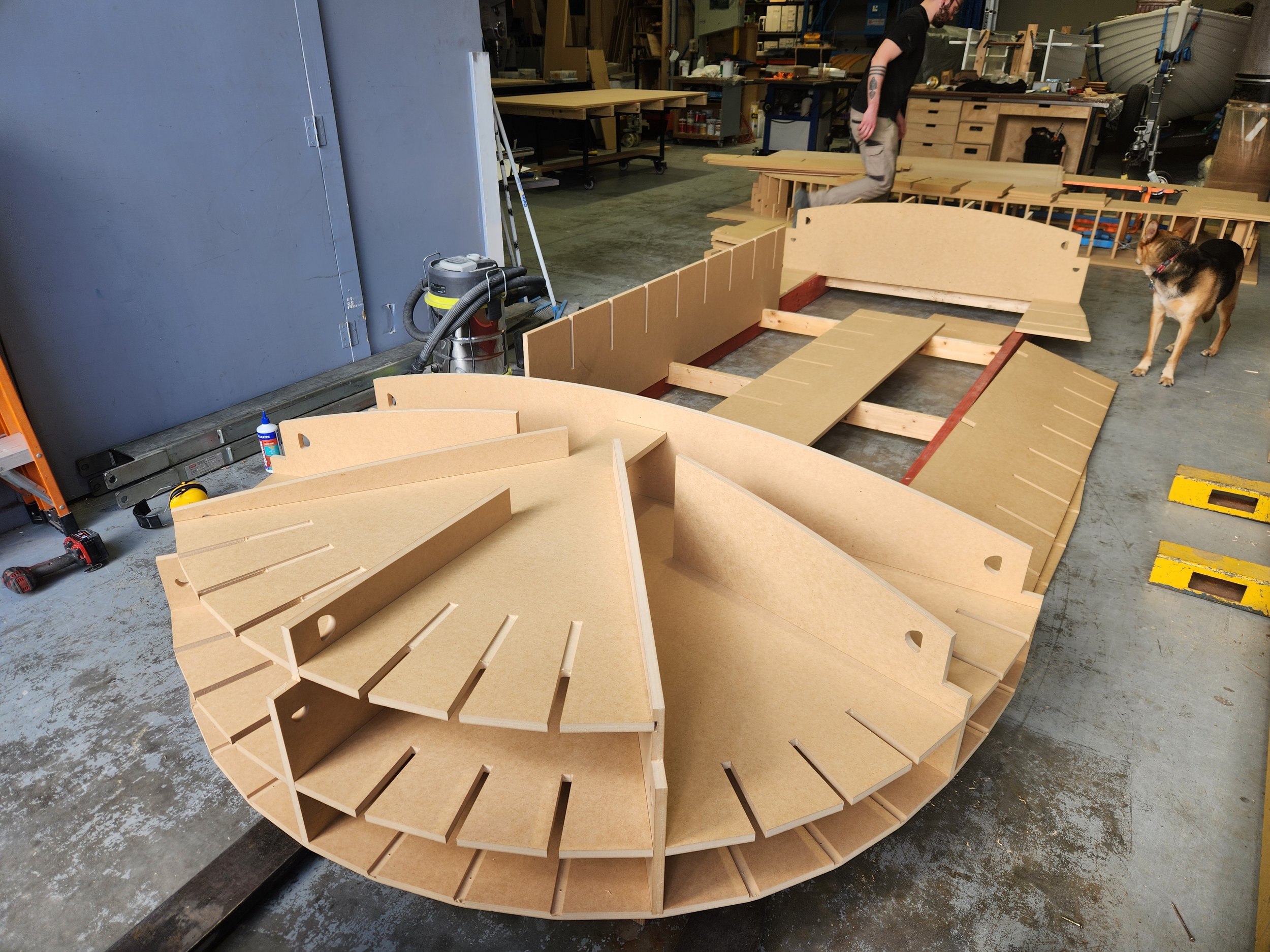
CAD preparation defines the component geometry.
CNC programming then determines how the approved geometry will be machined, including:
Cutter selection
Toolpaths
Cutting depths
Machining order
Entry and exit methods
Workholding
Part spacing
Sheet nesting
Tabs or other part-retention methods
Machine setup
These are connected stages, but they are not the same task.
Depending on the project, file preparation, CNC programming, material and machining may appear as separate items within the quote.
Clean component geometry reduces unnecessary preparation, but every job still requires production review and CNC programming before machining.
BEFORE THE FILE IS APPROVED
The Drawing Must Match the Material and Machining Process
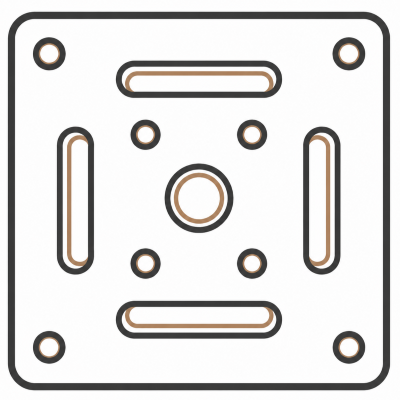
Material and Thickness - Nominal sheet thickness and actual measured thickness can differ. This is particularly important for slots, rebates, fitted joints and assemblies.
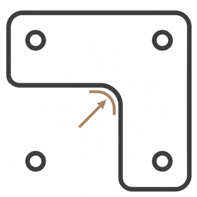
Profiles and Internal Corners - A round CNC cutter leaves a radius in internal corners. Reliefs or other details may be required where a square component must fit into that corner.
Holes, Pockets and Rebates - The file or accompanying instructions must identify which details pass through the material and which stop at a controlled depth.
Handed and Mirrored Components - Left-hand, right-hand and mirrored components should be named and checked clearly before production.
Grain and Face Direction - Where appearance or strength depends on grain direction, veneer face or material orientation, this should be marked before nesting.
Quantities and Revisions - The current quantity and approved revision must be supplied together. Older files or quantity lists should not remain mixed with the current production information.
Fitted Parts - Joints, slots and locating features may require test cuts using the actual material before the final geometry is approved.
A CONTROLLED PROCESS
The Required CAD Work Is Scoped Before It Begins

Send the Current Information

We Review the Starting Point

We Define the Preparation Scope


We Prepare the Geometry

You Approve and Move to Cut It
Upload drawings, PDFs, CAD files, models or sketches
Include measurements, photographs and references
Identify the required components
Note what is confirmed and what is unresolved
Check what information is usable
Identify geometry that can be retained
Flag missing dimensions or unclear details
Confirm whether the project is ready for Draw It
Return unresolved design decisions to Dream It
Confirm the components to be prepared
Confirm the source information
Define the required drawing, modelling or file repair
Identify machining details or test pieces
Quote or authorise the paid preparation work
Redraw, repair or separate the agreed parts
Prepare the components for review
Resolve questions raised during preparation
Match the geometry to the agreed material and thickness
Organise the files for production
Review the prepared geometry
Confirm dimensions, material and quantities
Confirm machining details
Approve the current revision
Move to Cut It for CNC production
PROJECT INFORMATION
Send the Most Dependable Version of the Project
Provide as much of the following as possible:
All current drawings and files
A plain-language description of the required parts
Overall and critical dimensions
Material, grade and thickness
Required quantities
Profiles, holes, pockets and rebates
Grain or face direction where relevant
Handed and mirrored component information
Assembly or fit requirements
Photographs of the existing item or intended use
The current revision
Required timing
Whether this is a one-off, prototype or repeat job
Any known details that still need to be resolved
Please remove outdated files where possible or clearly mark the version that should be reviewed.
NOTE: Do not combine several conflicting revisions without identifying which one is current.
SCOPE BOUNDARIES
Draw It, Is a Production Preparation Service
Unless specifically included in the agreed scope, Draw It does not automatically include:
Broad concept or product development
Engineering or structural calculations
Architectural or regulatory approval
Site measurement
Responsibility for unverified customer dimensions
Unlimited revisions
Complete assembly documentation
Presentation drawings or visual renders
Ownership or supply of WCW production files
CNC machining, material or workshop labour
Installation
Correction of changes made after approval
Confirmation that the customer's design is suitable for its final use
The exact CAD outputs and any customer file handover should be agreed before work begins.
The customer remains responsible for approving the final geometry, dimensions and intended use.
THE NEXT PRODUCTION STAGE
Move Forward When the Project Is Ready
Return to Dream It
Choose Dream It when important decisions about the product, construction, dimensions or intended result remain unresolved.
Move to Cut It
Choose Cut It when the component geometry, dimensions, material, thickness, quantities and machining requirements are approved.
Continue to CNC Cutting From Files
Add Build It
Choose Build It when the CNC-cut components also require agreed workshop work such as laminating, sanding, edgebanding, trial assembly or finishing.
View Component Assembly and Workshop Services
Some projects may only require one stage. Others may move through Dream, Draw, Cut and Build as separate quoted parts of the same project.
Start With Your Project Type

Custom Design and Projects
One-off ideas, product concepts and paid project development.
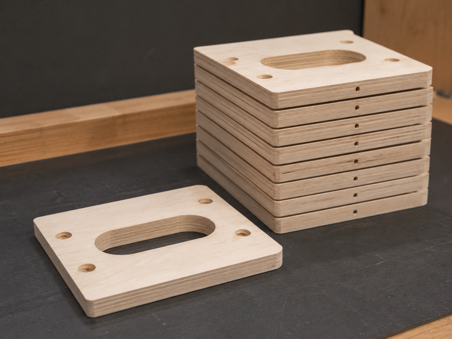
Small-Batch Production
First runs, repeat batches and controlled production parts.
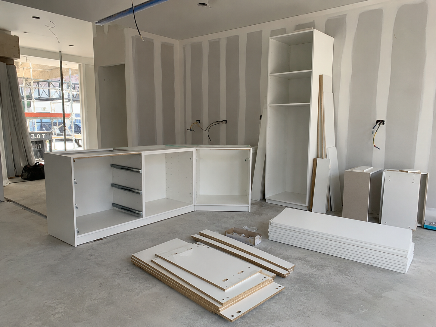
Construction and Trade
Panels, formers, fitout parts and CNC-cut trade components.
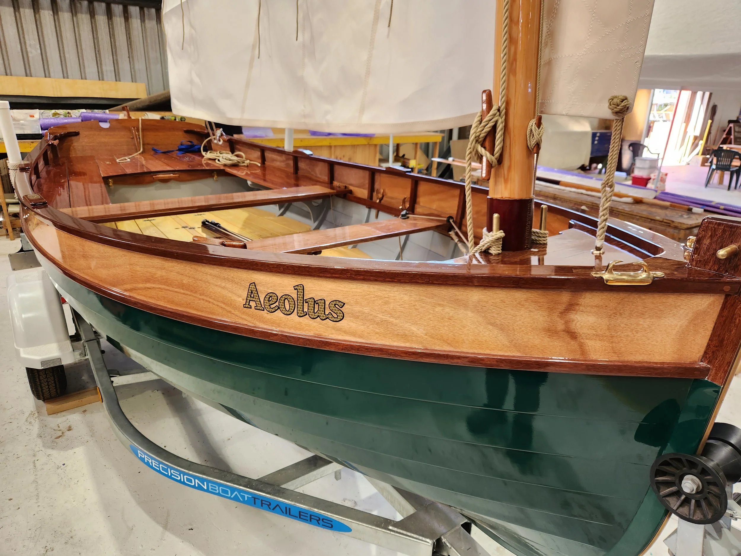
Boatbuilding and Marine
CNC-cut marine parts, patterns and fitout components.
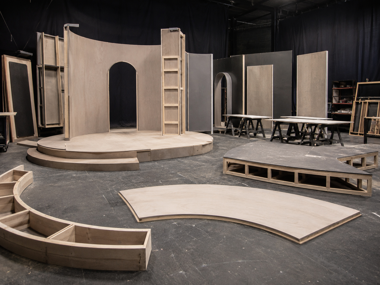
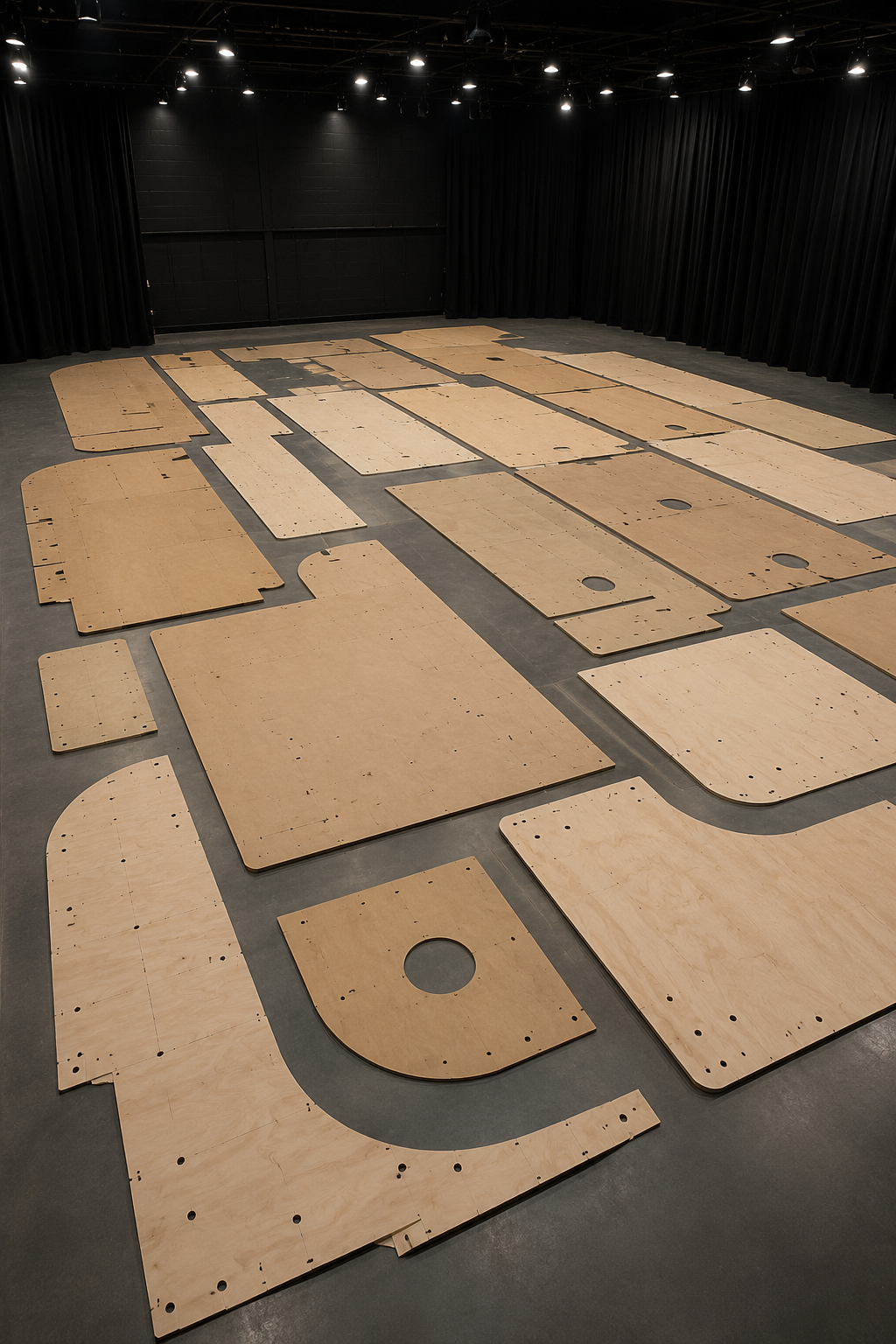
Set, exhibition and fabrication parts
CNC-cut parts for sets, displays and temporary builds.
RELATED PROJECT PATHWAYS
Templates and Patterns
Reusable guides, patterns and workshop templates.
Draw It Frequently Asked Questions
-
Sometimes a PDF contains useful vector information, but it should not be assumed to be ready for CNC production.
Scale, dimensions, geometry and machining details still need to be checked. Some PDFs must be redrawn before they can be used reliably.
-
Yes, where the sketch contains dependable dimensions and clearly explains the required components.
A rough sketch showing only an idea may need to begin under Dream It before detailed component geometry can be prepared.
-
Often, yes.
The file must first be reviewed to determine whether it needs a small cleanup or substantial reconstruction.
The amount of repair work is quoted according to the condition and complexity of the information supplied.
-
Yes, depending on the format and how the model has been created.
A complete model may still require individual components to be extracted, flattened, checked and prepared for the selected material and machining process.
-
Sometimes.
The reference must be inspected to determine how it can be measured or digitised and what level of accuracy is realistic.
Worn, distorted or damaged patterns may require interpretation rather than direct copying.
-
Not automatically.
CAD preparation, CNC programming, material, machine time and workshop services are separate parts of the project scope.
They may be combined in one overall quote where the required information is sufficiently clear.
-
The required deliverables should be agreed before the work begins.
Some work is prepared specifically as internal production geometry for machining by Williamstown CNC Works. Customer file supply, manufacturing drawings or other CAD deliverables may require a separate agreed scope.
-
Williamstown CNC Works reviews the geometry against the supplied and agreed information.
The customer remains responsible for checking and approving the dimensions, design, quantity and intended use before production begins.
-
No.
Where engineering, structural, architectural, marine, regulatory or specialist approval is required, it must be supplied by an appropriately qualified party.
-
The project moves into Cut It, where the approved geometry is programmed, nested and machined in the selected material.
Selected assembly or finishing work can also be considered under Build It.